
What is the Internet?
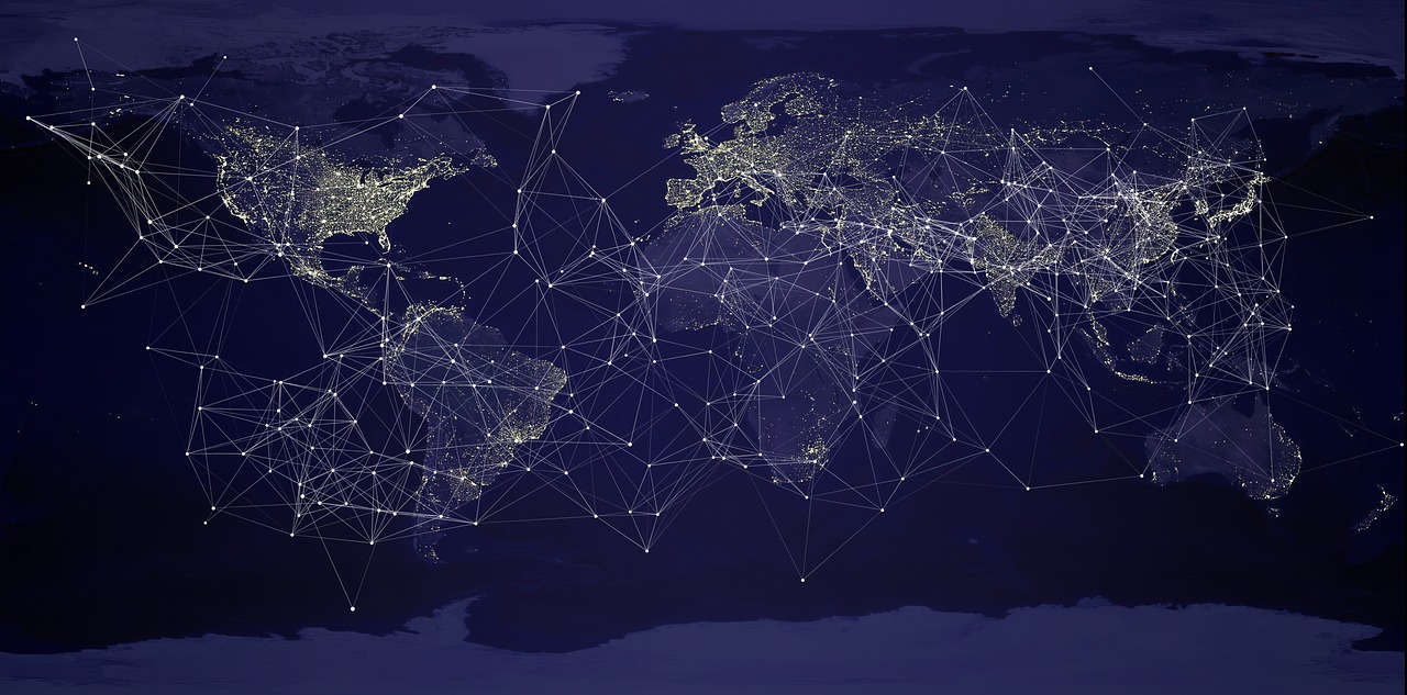
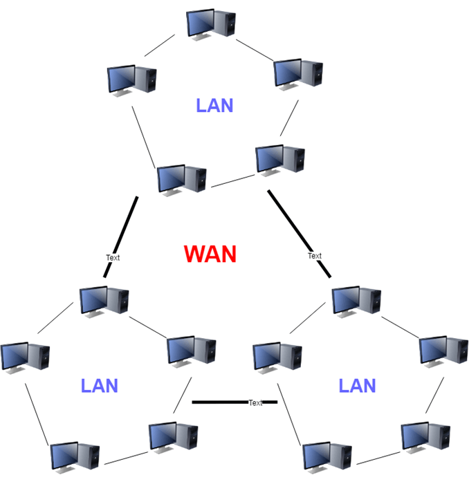
A network can be defined as a connection between 2 or more computers (e.g. via a LAN cable). The internet is a network of networks. It is a collection of separate networks spanning a large geographical area, linked together through a network infrastructure comprising of routers, cables and other physical devices. The internet is an example of a wide area network (WAN).
During day-to-day interactions on the web, the internet is used by applications on different devices to communicate with each other. Data from one device must travel through this network of sub-networks to reach the destination device.
Between networks, routers are needed to direct traffic. Routers act as gateways into and out of networks.
The internet comprises the infrastructure and the networking protocols that make communication between devices possible.
Networking Protocols
To ensure that computers and applications on a network understand each other during communication, we need to employ communication protocols. From wikipedia, a protocol is:
a system of rules that allow two or more entities of a communication system to transmit information.
Before it can be used, a communication protocol has to first be agreed upon by the parties involved.
Common protocols used on the internet include:
- IP
- SMTP
- TCP
- HTTP
- Ethernet
- FTP
- DNS
- UDP
- TLS
There are a lot of networking protocols. They are essentially different systems of rules designed to address different aspects of network communication. Some protocols are created to address the same aspect of network communication, but for different use-cases.
Network Communication as a Layered System
Communication systems can be complex. To study them, it is helpful to create a mental model by categorizing their different aspects into layers.
Two popular models to conceptualize networking systems are: the Open Systems Interconnection (OSI) model, and Internet Protocol Suite.
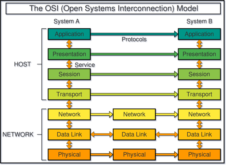
The OSI model divides network communication into 7 layers:
- Physical Layer
- responsible for transmission of raw data or bits over a physical medium
- examples of technologies include ethernet cables and hubs/switches
- examples of physical medium include electric voltages, radio frequencies, and light.
- Data Link Layer
- include protocols concerned with identification of devices on a physical network, and the movement of data between these devices
- the Ethernet protocol is a common protocol at this layer
- Network Layer
- handles the routing of data between devices on different networks.
- determines the best physical path for data delivery
- Internet Protocol (IP) is used.
- Transport Layer
- responsible for chopping up data from the application layers into smaller pieces for transfer, and ensuring that all these pieces arrive at the destination for the correct applications (via port numbers).
- Session Layer
- management of logical connections between networked applications. But this function is actually handled by the Application and Transport layers when using HTTP and TCP.
- Presentation Layer
- handles translation, encryption and compression of data
- Application Layer
- includes protocols used by applications to communicate with each other.
The Internet Protocol Suite is a 4-layer model:
- Network Access Layer
- defines how data is physically sent over a network
- Roughly maps to the Data Link and Physical layers in OSI model
- Internet Layer
- responsible for packing information into data packets, which contain the source and destination addresses used to forward the packet across networks.
- roughly maps to the Network layer in OSI model
- Transport Layer
- roughly maps to the Transport layer in OSI model
- Application Layer
- includes protocols used by applications to interface with data from the Transport Layer.
- example of protocols include HTTP, FTP, and SMTP.
- roughly maps to Session, Presentation, and Application layers of OSI model.
Data Encapsulation between networking layers
Data Encapsulation means data hiding. In the context of programming, it is the packaging of data and methods into a single component, which protects the data from undesired changes from the outside world.
In networking, data is encapsulated/packaged at each layer before it is presented to the next layer. A block of encapsulated data is known as a Protocol Data Unit (PDU). A PDU adopts a different name depending on the layer on which it is created.
A PDU consists of a header, a data payload, and sometimes a footer. Data encapsulation into PDUs enables abstraction between networking layers. Different protocols can therefore be used at each layer without the lower layer needing to worry about what sort of data is being packaged from the layer above. This separation of concerns allows for independent evolution of networking standards and technologies.
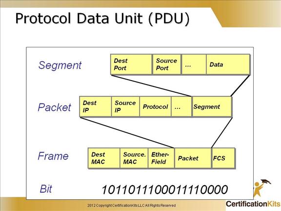
Image Source: https://www.certificationkits.com/
Local Area Network
Once data has finished travelling across the internet and arrived at a router of a local area network, it needs to be futher directed to the intended recipient/device. This happens at the Data Link Layer of the OSI model.
Protocol Data Units (PDU’s) on the ethernet protocols are called Ethernet Frames. Ethernet Frames encapsulate data from the Internet/Network layer. Among other header fields, a frame must contain the source and destination MAC addresses.
A Media Access Control (MAC) address is a 12-digit hexadecimal numbers embedded into a Network Interface Card of a device. It is a physical or hardware address that uniquely identified a device on a network. It is this MAC address that is used to direct the ethernet frame to/from devices in a LAN. A switch or router keeps a MAC address table containing MAC addresses of all devices on the LAN.
Wide Area Network
A Wide area network (WAN) is a network that spans a large geographical area. This is in contrast to a Local Area Network (LAN), which may be a network of home or office computers. The internet is an example of a WAN.
Data transmission over a WAN (or between different networks) is handled in the Network Layer of the OSI model. The Internet Protocol (IP) is the predominant protocol used, and the PDU in the IP protocol is known as a packet. The packet contains metadata as well as the data payload.
Devices over a wide area network such as the internet are uniquely identified with IP addresses. Within IPv4, IP addresses consists of 4 groups of 8-bit numbers separated by a ‘.’ e.g. 172.16.254.1
The maximum number of IPv4 addresses is 2 to the power of 32, or 4,294,967,296. To deal with the impending problem of IPv4 address exhaustion, IPv6 has been developed. An IPv6 address uses 128 bits, which allow for an exponentially higher number of possible addresses (equal to 2 to the power of 128).
Each network is allocated a range of IP addresses from the Internet Assigned Numbers Authority (IANA). IP addresses actually have a hierarchical structure. There is the network part of the IP address which is used to identify a particular network within a network of networks. Then there is the host part which identifies the exact location of a host computer that an IP packet is intended for within a subnetwork.
Routers do not know the exact location of the host computer for which an IP packet is intended. Routers know only what network a host computer is a part of, and uses information stored in the router’s routing table to deliver the IP packet to the destination host’s network/router. The host network’s router then delivers the packet to the host within the subnetwork.
Transport Layer
Once an IP packet arrives at a destination computer, where does it go? There are often multiple applications running on a computer. The IP protocol is merely responsible for transferring information between hosts. We need a way to allow data to reach its intended application. This is where the Transport Layer protocols come in - the two most common ones being Transmission Control Protocol (TCP), and User Datagram Protocol (UDP).
Similar to how IP protocol makes use of IP addresses to identify hosts on a network, TCP or UDP makes use of ports to identify applications on a host device. The combination of the IP address and the port is known as a socket.
Port numbers range from 0 to 65535. Each port can be used by a different application or service as a connection endpoint to communicate with other applications or services on another device over a network. Some port numbers are well-known or reserved for privileged services. Some examples of well-known ports are:
| Port | Service name |
|---|---|
| 20,21 | File Transfer Protocol (FTP) |
| 22 | Secure Shell (SSH) |
| 23 | Telnet |
| 25 | Simple Mail Transfer Protocol (SMTP) |
| 53 | Domain Name System (DNS) |
| 67,68 | Dynamic Host Configuration Protocol (DHCP) |
| 80 | HyperText Transfer Protocol (HTTP) |
| 110 | Post Office Protocol (POP3) |
| 119 | Network News Transport Protocol (NNTP) |
| 123 | Network Time Protocol (NTP) |
| 143 | Internet Message Access Protocol (IMAP) |
| 443 | HTTP with Secure Sockets Layer over TLS/SSL |
The Protocol Data Units (PDUs) in TCP is known as a segment; in UDP it is a datagram. Both protocols use headers in their PDU’s to contain the source and destination port numbers. Before being sent over a network, the whole PDU in the Transport Layer is then encapsulated as the data payload for the IP protocol in the Network Layer, where the source and destination IP addresses are added in.
The ability for multiple applications to transfer data over a single channel is known as multiplexing. Multiplexing in general refers to the ability for multiple signals to be gathered together and travel over a single channel. Reversing this process to unpack signals and deliver them to their respective applications is known as demultiplexing.
Ensuring Reliable Data Transfer
Data transfer below the Network Layer are inherently unreliable. Data can be lost along the way. If the data is corrupted (verified using checksums), it may be discarded by the IP protocol on the Network Layer, or the Ethernet protocol on the Datalink Layer. In either case, it may be undesirable to have missing data on the receiving end of a connection. This problem is addressed in the design of the TCP protocol.
TCP is the most common protocol used in the Transport Layer. It features reliable data transfer from source to destination. Before actual data transmission, TCP first establishes a connection between the sender and receiver via a 3-way Handshake. During data transmission in TCP, the receiver continually sends messages of acknowledgement back to the sender on receipt of data. If acknowledgement is not received by the sender, data will be re-transmitted.
Other features of TCP include:
- ordering of network packets during transmission by attaching a sequence number to each packet.
- flow control - prevents a sender from overwhelming the receiver by sending too much data at a time
- congestion avoidance - prevents devices on a network from overwhelming the network with data
Data reliability comes at a cost of performance. TCP connections and data transmission involve overhead operations to ensure reliability. This can create a source of latency (e.g. a browser needing to establish dozens of TCP connections to load a high number of resources on a webpage). For applications that do not require strict reliability or in-order delivery of data packets, UDP is an alternative protocol. A example use-case is a video-chat application that exchanges occasional loss of pixels for an increase in performance.
Application Layer
The functions of Presentation and Session layers often blend in either with the Application Layer or with the Transport Layer. See here for more information on these 2 layers.
The Application Layer contains protocols that applications interact with or use to communicate across networks. This layer is not the applications themselves. It provides applications access to the underlying network.
Protocols on the Application Layer are implemented within the networked applications themselves. These protocols define the syntax, type and structure of messages passed between applications so that the exchanged data can be correctly interpreted. Here are some common application protocols:
| Application Protocol | Port |
|---|---|
| Domain Name System (DNS) | TCP port 53 |
| HTTP | TCP port 80 |
| HTTPS | TCP port 83 |
| Simple Mail Transfer Protocol (SMTP) | TCP port 25 |
| Telnet | TCP port 23 |
| FTP | TCP ports 20 and 21 |
Different application protocols provide different services on the internet. For example, the File Transfer Protocol (FTP) is used to transfer files across networks, while the Internet Message Access Protocol (IMAP) enables management of email messages. For the rest of this article, we’ll explore the HTTP protocol, which is used for accessing webpages.
HTTP
HTTP is the most widely-used application protocol on the internet. It is used to access the World Wide Web (WWW), a.k.a The Web. The Web is an information system of documents/images/video/audio files identified by their Uniform Resource Locators (URLS). A URL is structured in the form of scheme://host:port/path?query. An example of a URL is http://google.com, where http is the scheme, google.com is the host name, 80 is the default port used by HTTP, and ‘path’ and ‘query strings’ are optional.
HTTP is the protocol used every time you access a website. It works via Request-Response cycles. HTTP is stateless, meaning that each Request-Response cycle should work independently without reliance on any state/information from prior exchanges. HTTP messages are also text-based.
Let’s see what a typical HTTP Request-Response cycle looks like, starting from when you enter a web address into a web browser:
You enter http://www.google.com into a web browser such as Chrome. In order to create a connection using TCP (Transport Layer), an IP address is needed. This can be looked up by the browser or the underlying operating system by sending a DNS request (containing the hostname to be looked up) to a DNS server via the Domain Name System (DNS) protocol. Once an IP address is obtained, the a TCP connection can be established via port 80 - the default port for HTTP.
With a TCP connection in place, the browser is ready to issue a HTTP Request to the google server.
HTTP Request
The HTTP Request has several components. From our example, it looks like:
GET / HTTP/1.1
Host: www.google.com
The request line is the first line in the Request. It consists of
- a HTTP method
- in our example, we used the HTTP GET method, which is used to retrieve data from a server.
- Another method is POST, which is used to send data to a server.
- the path, which identifies the resource being sought after.
- the HTTP protocol version number
The next part that comes after the request line are HTTP headers. They provide additional information related to the HTTP Request, and are structured in colon separated name-value pairs. In HTTP 1.1, the host request header must be included to identify the hostname the client is requesting.
A HTTP Request can optionally have a message body. When a POST method is used, the message body contains the data that needs to be sent. In our example which uses the GET method, the message body is empty.
HTTP Response
The reply we receive from Google consists of:
- a status code
- response headers
- a message body
The status code along with response headers look like:
HTTP/1.1 200 OK
Date: Sun, 01 Mar 2020 02:05:47 GMT
Expires: -1
Cache-Control: private, max-age=0
Content-Type: text/html; charset=ISO-8859-1
Server: gws
X-XSS-Protection: 0
X-Frame-Options: SAMEORIGIN
Accept-Ranges: none
Vary: Accept-Encoding
Transfer-Encoding: chunked
HTTP status codes signify the result of a request. The codes are grouped into 5 categories:
- Informational responses (100–199)
- Successful responses (200–299)
- Redirects (300-399)
- Client errors (400-499)
- Server errors (500-599)
In our example, status code 200 along with the status text OK means the request has succeeded.
Response headers provide additional information about the response (which may assist the client in displaying the results). For example, the header Content-Type indicates that the format of the content is text/html.
The message body of a response contains the actual resource requested by a client. If an error happened, the message body can contain information about the error. In our example, the message body contains the HTML code that can be used by the client browser to display the google home page.
Security

HTTP messages are in plain-text, which poses a security risk. Messages may be read by unauthorised parties along the way, or they can be tampered with during transit.
Transport Layer Security (TLS) protocol is a cryptographic protocol designed to offer 3 services when implemented on top of Transport Layer protocols such as TCP:
- encryption - to ensure data cannot be read by eavesdroppers
- authentication - to verify that data is being transmitted between intended parties
- integrity - to ensure data has not been tampered with during transit
TLS Encryption
To achieve encryption, a TLS Handshake is performed straight after a TCP 3-way handshake when establishing a connection. During a TLS handshake, the parties agree on which cryptographic protocols to use, and exchange cryptographic keys that will be used to encrypt subsequent data transmissions.
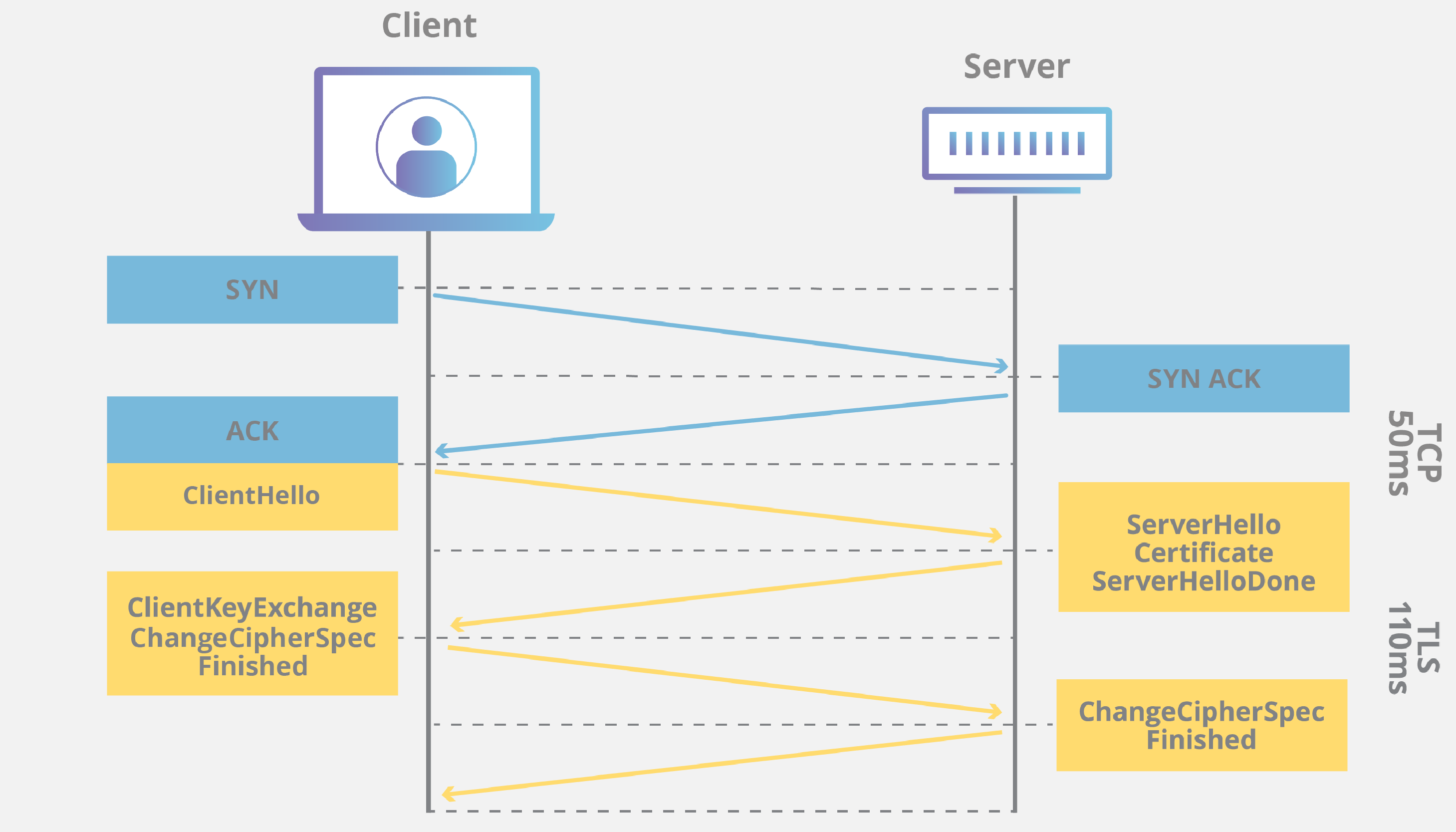
TCP + TLS Handshakes. Source: https://www.cloudflare.com/learning/ssl/what-happens-in-a-tls-handshake/
TLS Authentication
To purpose of authentication is to ensure a party on the other end of a communication channel is who they say they were. E.g. when you visit a banking website, you want to be sure that you are communicating with the authentic server of the banking corporation, and not some impersonator.
Authentication is achieved via TLS Certificates. During a TLS Handshake, the server provides a digital certificate to the client. Certificates are issued by Certificate Authorities (CA’s) who verifies the identiy of whoever requests a certificate. The digital certificate contains a public key and a digital signature (generated using the a private key held only by the server). The client uses the public key to verify that the signature is legitimate, which means that communication has come from the authentic owner of the digital certificate.
TLS Integrity
TLS ensures the integrity of data by including a Message Authentication Code (MAC) as part of its PDU/data packet. This code is generated using a hashing algorithm agreed upon during TLS handshake. On receipt of the data packet, the client generates its own MAC based on the data payload. The two MAC’s will match if the data has not been changed during transit.
Final Recap: The Journey of a Data Packet
Let’s re-use our HTTP example from earlier, and start with a user entering http://www.google.com into their web browser. What happens next?

We start on the Application Layer. A HTTP Request is generated by the browser application. This gets packaged into a PDU that gets passed to the layer below - the Transport Layer (we skipped Presentation and Session layers in this example due to the cross-over of functions with their adjacent layers).
The HTTP message from the Application Layer becomes the data payload in the Transport Layer. The TCP protocol packages this data along with source and destination ports (along with other headers) into a PDU known as a TCP Segment. The Segment gets passed onto the Network Layer below.
In the Network Layer, the TCP segment becomes the Data Payload. This payload gets combined with the source and destination IP addresses (along with other headers) into a PDU known as an IP Packet. This packet gets passed onto the Data Link layer.
In the Data Link Layer, an Ethernet Frame is created which contains the IP packet as the data payload along with header information such as the source MAC address. The Ethernet frame is then pushed on the physical layer.
The raw data bits are transferred over physical distances (via cables, wirelessly, and through routers) to arrive at the local network of the destination device. The raw bits then gets unencapsulated all the way back up the layers to reach the intended server application of Google for handling the original HTTP request.